
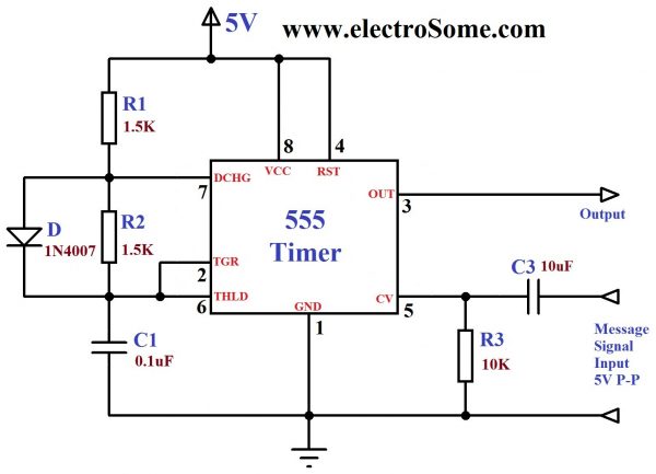
Study of FM modulation and demodulation Transmitter and Receiver Circuit Diagram The heart of the Fsk modulation circuit using 555 timer is the 555 timer IC itself. This chip is used to create an adjustable oscillator which is capable of generating a wide range of frequency shifts. By shifting the frequency of the signal from one point to another, it is possible to modulate the incoming signal into various tones or data.

In pulse width modulation, a high frequency train of electrical pulses is sent to the device to power it. The pulses can be generated by a drive transistor or power MOSFET. In the circuit above, we see a 555 timer configured as an astable oscillator. The 555 timer will generate the pulse width modulation signal at a specific duty cycle and An FM circuit typically consists of four main parts: Modulator: The modulator combines the carrier wave with the input signal to produce a frequency-modulated signal. This is where the actual frequency modulation takes place. Frequency Stabilizer: This component stabilizes the frequency of the carrier wave, ensuring a steady, unvarying
How to Build a Pulse Width Modulation Signal Generator Circuit Diagram
For the purpose of the demonstration of AM modulation one circuit is tuned to generate a high frequency around 4 KHz and the other circuit is tuned to generate a frequency of around 500 Hz. The 4 KHz circuit acts as the carrier generator and the low frequency 500 Hz sine wave circuit acts as the message signal generator. AM Modulator. AM Building a frequency modulation circuit. The FM modulator circuit (frequency modulation) is built with a Motorola MC1648P oscillator. Two varactors, Motorola MV-209 are used to frequency modulate the oscillator. The 5000 Ω potentiometer is used to bias the varactors for the best linearity. The output frequency of approximately 100 MHz can be

Furthermore, the loop bandwidth (LBW) will determine the usable modulation frequency. If the modulation is applied to the RefClk, the maximum modulation frequency will be less than the LBW because the loop filter is low-pass-filtered to the RefClk. In fact, the minimum modulation frequency has to be greater than the LBW if the modulation is This versatile design and simulation software makes it easy to create and analyze complex circuit diagrams of all kinds, including those related to frequency modulation. The software allows users to easily add components, connect them, and simulate the circuit's performance.
I want to build a Frequency Modulation circuit Circuit Diagram
With a little cleverness, you can have a modulation signal change how fast the capacitor is charged and discharged, which in turn effects the oscillator frequency. This can be done digitally too. For FM, use a hardware PWM generator built into a micro, and adjust its period based on the modulation signal. For AM, a hybrid approach is possible.

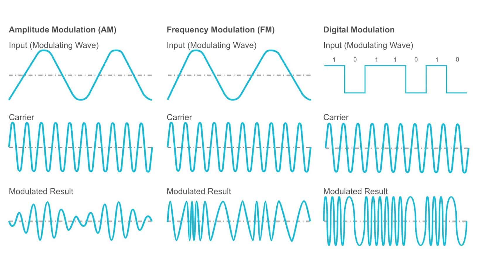
The higher frequency signal is the carrier frequency, while the original signal is the data that you want to relay. We will use the data signal to modulate a much higher frequency carrier wave. Later we will filter out the carrier and recover the data. The first three sections of the schematic are the modulation circuit.
