AUDIO AMPLIFIER using single transistor Circuit Diagram This is a 4 transistor audio amplifier circuit. Which is a 4-transistors complementary push-pull amplifier, that shows the basics of audio amplifier design. This circuit saving on battery current, which is quite low with middle volume, rising to 25 -30mA as a volume is increased. There are many amplifier circuits using transistors. You may

By this we can easily use transistor as a linear amplifier in active region. Read the post: Transistor Basics to know more about transistors. Common Emitter RC Coupled Amplifier: Common emitter RC coupled amplifier is basic and simple amplifier. The circuit of RC coupled amplifier is shown below. The TIP120 Darlington transistor is a type of bipolar junction transistor (BJT) that can be used in amplifier circuits. In a simple common-emitter amplifier circuit using a TIP120, increasing the supply voltage can cause an increase in the collector current, which can in turn increase the output signal amplitude and potentially the volume level. Therefore, when using the transistor audio amplifier, the circuit works in the active phase. In this experiment, it will take you to learn a simple amplifier circuit. Let's get started. These circuits are simple amplifiers you can look other HERE Small transistor amplifier circuits. We have 2 interesting experiments. Simple Microphone audio

Simple Basic Audio amplifier with BC547 Transistor Circuit Diagram
This Simple Single Transistor Audio Amplifier circuit is a simplistic preamplifier circuit. But before understanding its works, you must know what are the preamplifier circuits. usually, any type of audio amplifier uses two basic amplification circuits, the pre-amplifier, and the main amplifier.
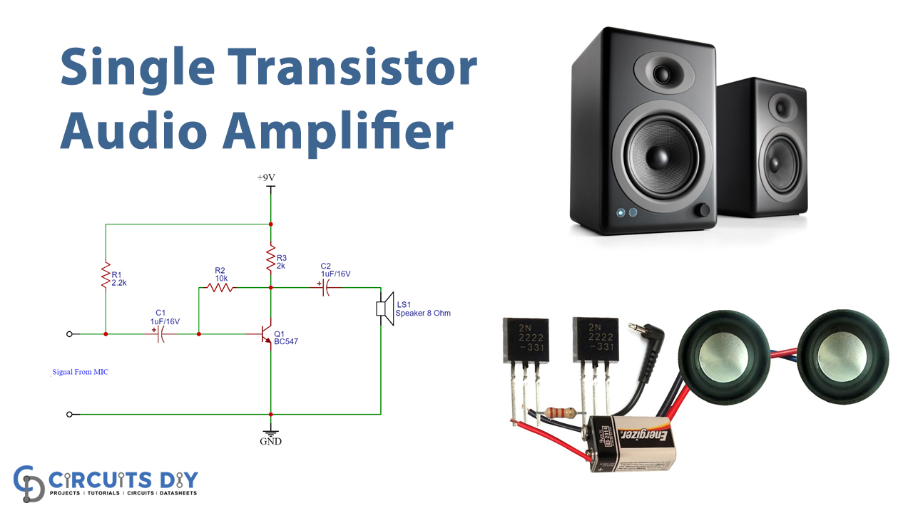
This audio signal is then given to the base of the transistor through the 100uf capacitor. The capacitor triggers the NPN transistor therefore the transistor starts operating. The transistor magnifies the audio signal. The transistor is wired in a common emitter configuration. Therefore emitter is grounded and output is taken at the collector.

RC Coupled Amplifier Circuit - Electronics Hub Circuit Diagram
Learn how to design audio circuits, Build an audio amplifier with excellent sound quality using the LM1875 audio amplifier chip. Step by step instructions and schematics included. Ultimate Guide to Op-Amps - Part 1 Need a guide in designing your own transistor amplifier? Learn here the basics of gain, calculating gain, biasing, among