

Powered Surveillance Balancing Security and Personal Freedoms Circuit Diagram The intruder gets detected by the

Analysis of Circuits Circuit Diagram
Analysis of Circuits Circuit Diagram We will use three physical quantities in our analysis of

IoT Vending 4 1 Circuit Diagram
IoT Vending 4 1 Circuit Diagram An IoT-enabled smart vending machine with the integration of

Infrared Sensor Complete Guide Circuit Diagram
Infrared Sensor Complete Guide Circuit Diagram IR Sensor Pinout. The IR sensor has a 3-pin

Securing Underwater Wireless Communication 72D Circuit Diagram
Securing Underwater Wireless Communication 72D Circuit Diagram Hi all, this is my first post here,

Voice First Approach to Home Assistant Circuit Diagram
Voice First Approach to Home Assistant Circuit Diagram The Voice-Controlled Smart Home Assistant is an

Voice Gesture Controlled Home Automation Circuit Diagram
Voice Gesture Controlled Home Automation Circuit Diagram 1. Gesture based light control 2. Gesture controlled
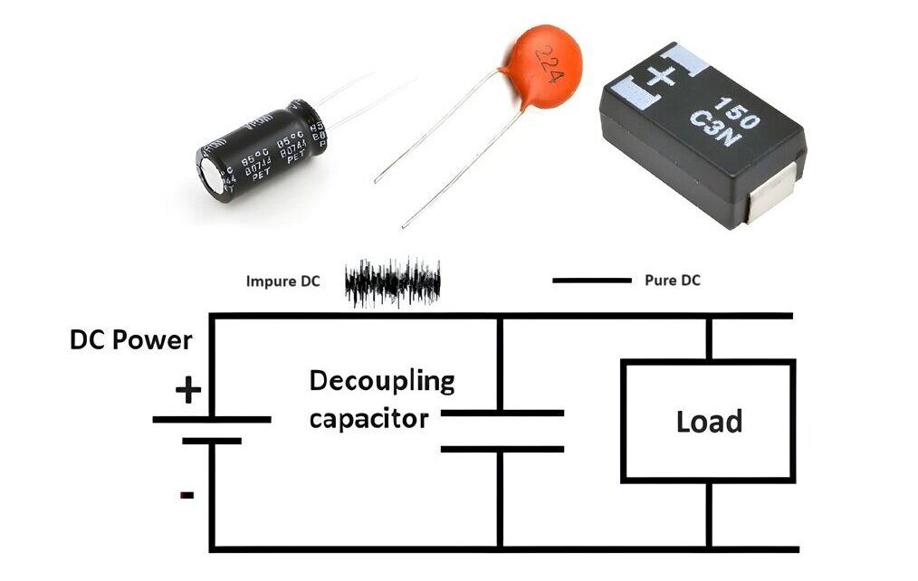
Decoupling Capacitor Working and Uses Hackatronic Circuit Diagram
Decoupling Capacitor Working and Uses Hackatronic Circuit Diagram In this blog, we will explore the

How to make Water Pump Automatic Switch ON Circuit Diagram
How to make Water Pump Automatic Switch ON Circuit Diagram Simple automatic water level controller

Robot Hands Make a fun robotic hand that you can control Circuit Diagram
Robot Hands Make a fun robotic hand that you can control Circuit Diagram Overall, the

DC Step Down Regulator with 4 Outputs Circuit Diagram
DC Step Down Regulator with 4 Outputs Circuit Diagram It has a 1.25V reference regulator

Electronic Circuits Circuit Diagram
Electronic Circuits Circuit Diagram Tachometer is a RPM counter which counts the no. of rotations

Raspberry Pi Projects Home Automation Circuit Diagram
Raspberry Pi Projects Home Automation Circuit Diagram Raspberry Pi as home automation refers to the

The Role of IoT in Shaping the Future of Smart Building Automation Circuit Diagram
The Role of IoT in Shaping the Future of Smart Building Automation Circuit Diagram In
Low pass filter circuit Based on operational amplifier LF353 this Circuit Diagram
Low pass filter circuit Based on operational amplifier LF353 this Circuit Diagram Passive Low Pass
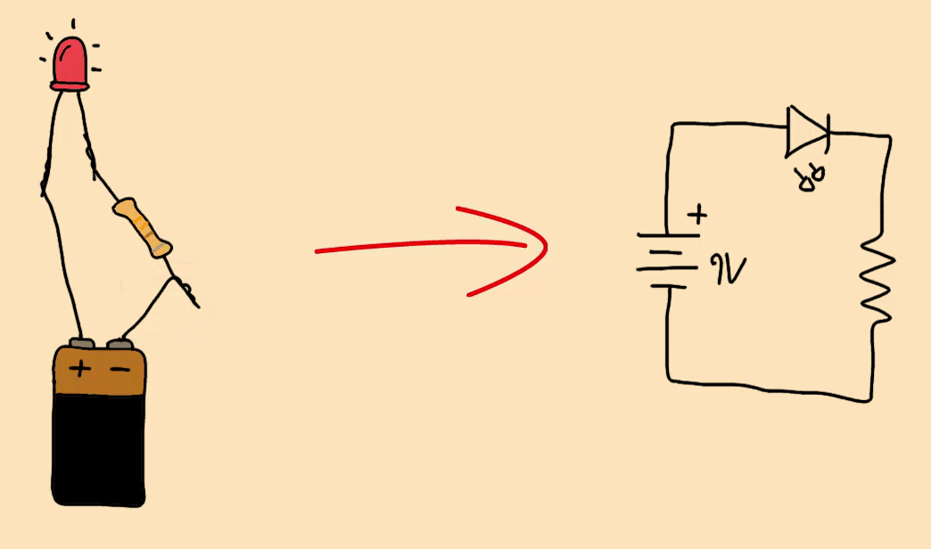
Learn Electronics With These 10 Simple Steps Circuit Diagram
Learn Electronics With These 10 Simple Steps Circuit Diagram Learn how to read and understand

Homemade Cell Phone Signal Booster Circuit Diagram
Homemade Cell Phone Signal Booster Circuit Diagram Circuit Diagram Working Explanation. In this Mobile Signal
GPS Trackers What It Takes to Create a GPS Tracking System Circuit Diagram
GPS Trackers What It Takes to Create a GPS Tracking System Circuit Diagram For tracking

Security Alarm System Schematic Diagram Circuit Diagram
Security Alarm System Schematic Diagram Circuit Diagram In this Instructables, you will know how to

Resistors 9 Steps Circuit Diagram
Resistors 9 Steps Circuit Diagram Choosing the right resistor for your specific application is key